Its time to build the cluster. I have all the parts described for my cluster in my prior post, and today’s goal is to get the computers set and fingered as described in my cluster network design. This is a rather long post as I cover both hardware and operating system set up. At the end of this process, we will have a cluster of computers that is ready to have application software installed. I suggest building all the nodes first before starting with the operating system installation.
Before you get started with these steps, I highly recommend that you start the download for the Ubuntu 18.04 LTS Server installation ISO. Note that the EGLOBAL S200 computers couldn’t use the live install ISO for some reason, but everything worked just find with the alternative (or old style) Ubuntu installer. You can download the latest version of that installer here. Select the “64-bit PC (AMD64) server install image” version.
Cluster Node Construction
The S200 computer comes in a very efficiently packed box. These are truly small computers, being about 5.5 inches long on each side and 2.5 inches tall. I was impressed how much capability is packed in such a small package. In the box you will find the computer, a power supply, a HDMI cable, VESA mount hardware, and screws for mounting an internal 2.5″ SSD.
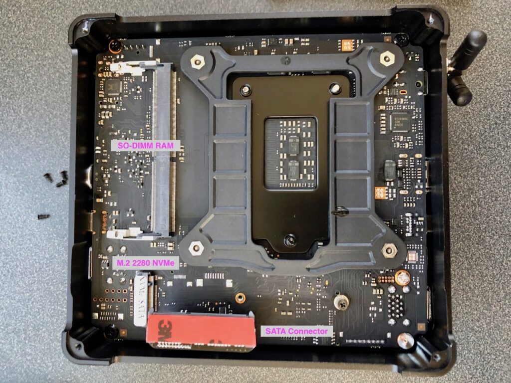
The top and bottom panels of the computer will need to be removed in order to install the RAM and SSD. The bottom panel is attached with small philips head screws, while the top panel is attached with T6 hex screws. I don’t know why they would use different screws on top and bottom, but just make sure you have both types of screw drivers before starting. The computer has two SO-DIMM RAM ports, one on the top side of the motherboard, and the second on the bottom. So you will have to open both sides to fully install the RAM.
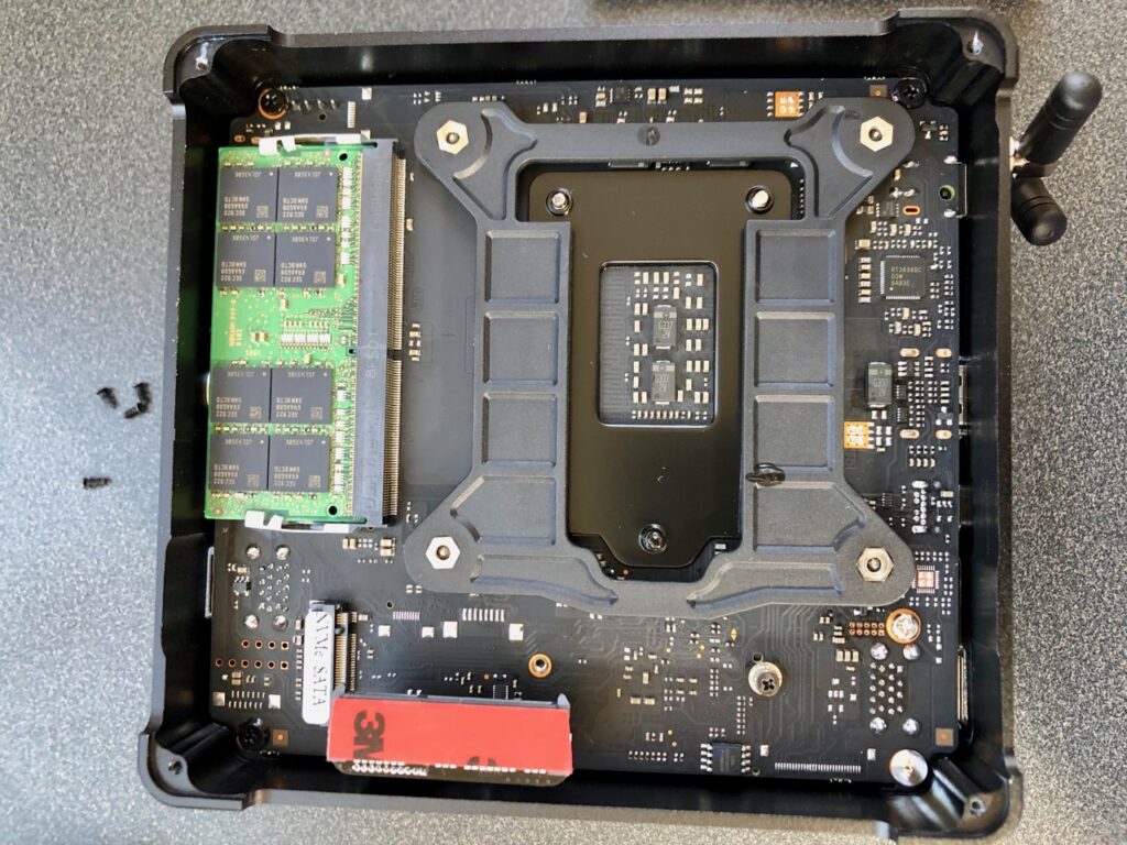
The first step I took was to install RAM on the bottom side of the computer. The bottom side also has a connector for a 2.5 inch SATA SSD and a M.2 slot for an NVMe SSD. There is also an M.2 slot on the top side of the motherboard. I decided I wOULD install the single M.2 SSD that I have on the top side, so the only thing I needed to install on the bottom side is one of the RAM modules. After doing so I reattached the bottom side cover.
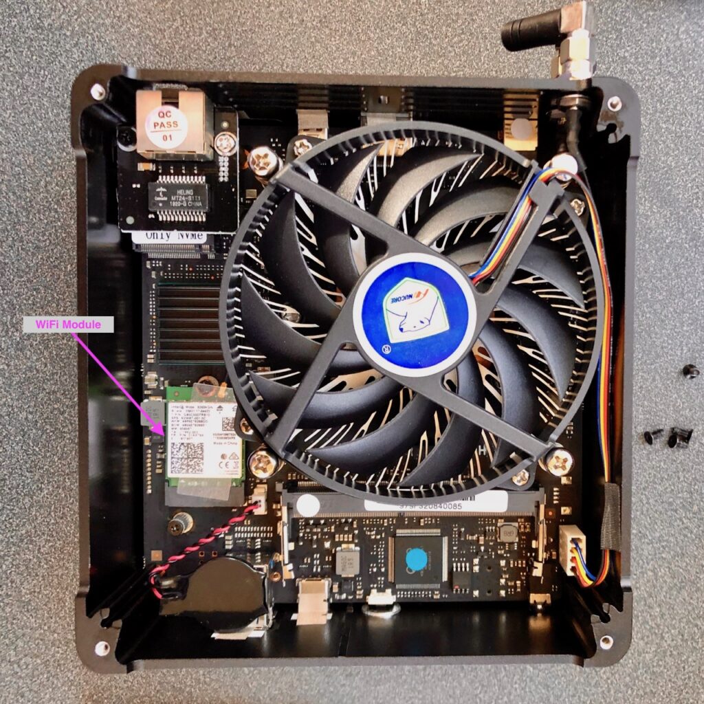
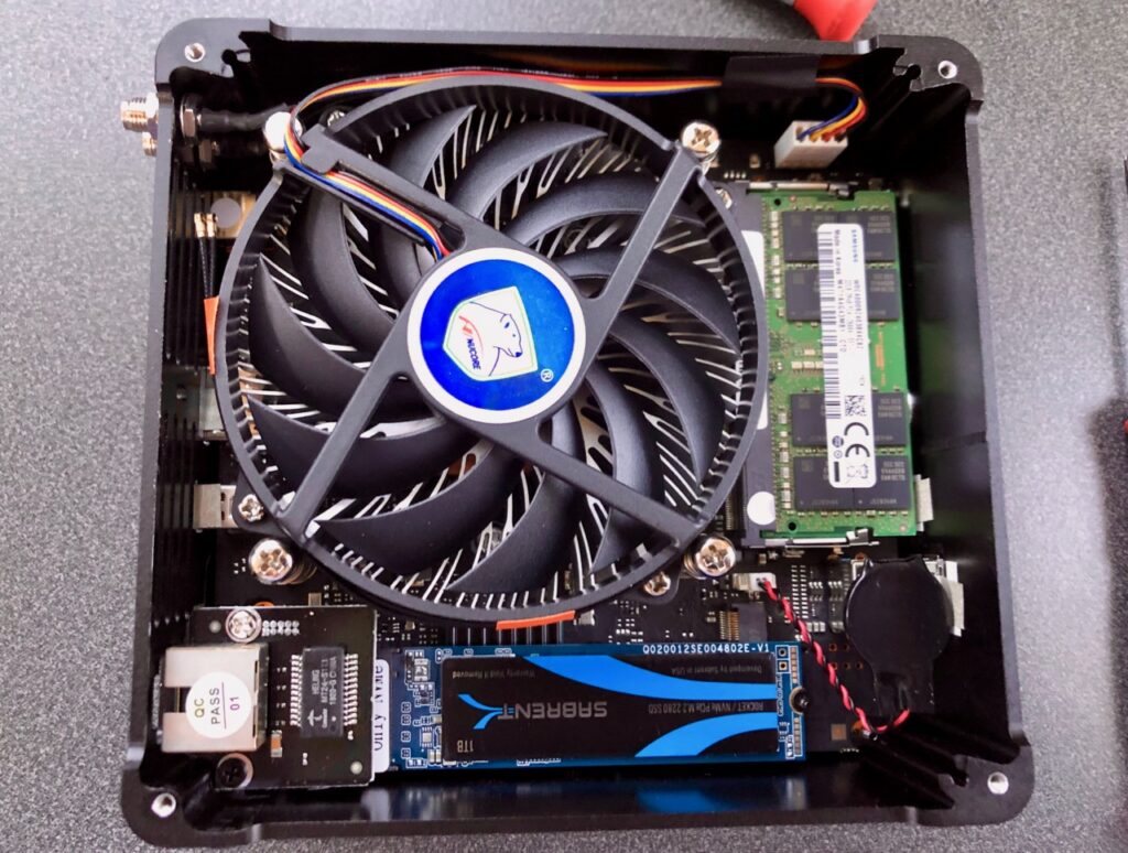
Next I will install a RAM module and the SSD on the top side. But before I do, I will remove the WiFi card. The reason for this is that I will not be using WiFi with these nodes, so I do not want to deal with configuring them out later. The challenge with removing them is that the manufacture attached a protective plastic piece on the top side of the card, ostensibly so that the antenna wires aren’t easily detached. With some careful prying, I was able to get to the mounting screw and then remove the card. Then I detached the antenna wires from the WiFi card. I considered removing these wires from the case connector on their other end, but I did not see an easy way to do so without disassembling more of the computer. I ended up simply using some electrical tape to tape the wires against the frame of the cooling fan. After doing that, the RAM module and M.2 SSD were easy to install. I also chose to remove the antennas attached to the exterior of the case since they too would not be used.
Once I was done with the top side, I reattached the cover, then connected the computer to a HDMI monitor and power for a quick power on test. In all cases, the computer booted to the BIOS screen just fine. The BIOS showed that the 64 GB of RAM were recognized and the 1 TB SSD was installed.
Repeat the buildout for all of the nodes. When done, arrange them next to each other, plug the power bricks into a power strip (but don’t connect to the computers yet), and place near the cluster the ethernet switch that was purchased to be the cluster’s internal networking backbone.
Operating System Setup
The installation of the Ubuntu Server 18.04 LTS operating system is mostly the same for all nodes, but how it will get configured will be different, especially for the master node. The master node is the node that will be connecting to the external network per my cluster networking design. It will act as a router for the slave nodes on the cluster’s internal network. For each node, there are three steps: install the operating system, configure the operating system, configure the SSD data partition. That last step is needed because we will be creating a different partition for the operating system and for the bulk data the cluster will hold. The reason for this is to separate the data from the operating system so that if we overflow the data contents of the hard drives it will not impact the operations of the operating system.
Installing the Operating System
Hopefully by now the Ubuntu Server ISO has completely downloaded for you. The next thing you need to do is create an installation drive with a USB drive. Ubuntu has some good instructions for how to do that here. Once you have created the install drive, you can start setting up the nodes. I strongly recommend that you completely set up the master node first, including the operating system configurations in the next section. The reason for that is given the cluster’s networking set up, the master node is the slave node’s internet router. You won’t be able to properly configure the slave nodes without an internet connection, and given the cluster’s network design the master node needs to be fully operating while the slave nodes are being set up.
To install the Ubuntu Server operating system, follow these steps:
- Connect the node being set up to a monitor and USB keyboard. Connect the node’s builtin ethernet to cluster’s internal network ethernet switch, which is the cluster’s LAN. If you are setting up what will be the master node, also connect the USB ethernet transceiver to the node’s USB C connector, and connect the USB ethernet transceiver to your home network.
- Insert Ubuntu Server install USB drive into one of the USB connectors on the computer, and turn computer on. The computer should boot into the Ubuntu installer.
- The first step in the installer is to configure the keyboard. Follow the instructions to do that.
- Next the installer will set up the computer’s networking. If you are setting up the master node, the installer will next say it found two network devices and will ask you to select the primary network connection. The “unknown” device is the USB ethernet transceiver, select that as primary, externally facing network connection (the WAN). The installer will then automatically configured it for a DHCP connection. On slave nodes, the installer will automatically set up the node’s internal ethernet connection without prompting you.
- Next the installer will ask for a computer name. On the master node call it “master”. For others “slaveX”, where X is 1, 2, or 3.
- Now you will set up your user account. Follow the prompts and create an account for yourself. I used the same account information on all nodes to keep things simple.
- The installer will now ask you how you want to partition the SSD. Select “Guided – Use Entire Disk” (do not select the LVM options). If you are given the option to select the device, select the one that looks like
/dev/nvme0n1. The installer will then set up the default partitioning on your SDD. It will then ask you if you want to write changes to disk; select No here, because we want to alter the the largest partition to break down into three partitions. You will now be presented with a screen that lists the partitions on the disk. Select the largest partition (likely partition #2), and on the next screen select “delete this partition”. It will return to the partition list screen, now select the large free space item at the bottom of the partition list. You will now get a menu that will ask what you want to do, select create new partition. Configure the first partition to be the boot partition described below. Repeat this process for each of the described partitions, then select the option to write the changes to disk- Name
boot, mount point/, size 64 GB, and formatted withext4. This will be the partition the operating system lives on. - Name
brick, mount point/mnt/brick, size 128 GB, and formatted withxfs. This will be the partition we run GlusterFS from. - name
data, mount point/mnt/data, size 100% of remaining space, and formatted withxfs. This will be the partition that the bulk storage of data and configuration will live.
- Name
- At this point the installer starts installing the operating system. Through out the installation, it will ask you for various configuration. Accept the defaults until you get asked about “software selection”. Select the “OpenSSH Server” option from that list and continue. There will be a few more questions, accept defaults. Then installation is done. Select the option to reboot, and when the computer restarts, pull out the USB drive that has the install media and the computer will boot to the login prompt.
Here you are done with the operating system installation. As stated above, if this was the master node you were working on, I strongly suggest you proceed to configure the master node before starting work on any of the slave nodes.
Configuring the Operating System
Master Node Configuration
To set up the master node, you will need to log into it. I strongly suggest you remotely SSH into the node rather than logging in via the keyboard and monitor attached to it. SSH will be your primary way of interacting with the cluster in general, so you might as well get started now. The first thing you need to do is figure out what the IP address that your home network’s router assigned to the master node’s USB ethernet dongle. I’ll leave that as an exercise for the reader. I also suggest that you configure your home network router to assign the master node’s USB ethernet transceiver a static IP address. That way you don’t have to rediscover its IP address with every reboot of the node. Once you know the master node’s IP address, SSH into it using the user credentials you set up during installation. Once in, you will likely be notified that there are updates available. Go ahead and install those updates:
sudo apt-get update
sudo apt-get upgrade
We now need to activate the built in ethernet on the master node to enable its connection to the cluster’s LAN. In Ubuntu 18.04, the networking system is called netplan. To set things up, we need to edit the netplan configuration file. First find the name of the network devices on the machine with the following command:
ip link
You should see an output that looks like this:
1: lo:  mtu 65536 qdisc noqueue state UNKNOWN mode DEFAULT group default qlen 1000
     link/loopback 00:00:00:00:00:00 brd 00:00:00:00:00:00
2: enp2s0:  mtu 1500 qdisc noop state DOWN mode DEFAULT group default qlen 1000
     link/ether 00:e0:4c:98:36:f1 brd ff:ff:ff:ff:ff:ff
3: enx70886b86dd68:  mtu 1500 qdisc fq_codel state UP mode DEFAULT group default qlen 1000
     link/ether 70:88:6b:86:dd:68 brd ff:ff:ff:ff:ff:ff
The third item on the list with the longest name is the USB ethernet transceiver. The other item that is not lo is the built in ethernet. Keep note of the device names, as we will need them later in a number of places. Next we need to edit the network plan:
cd /etc/netplan
sudo cp 01-netcfg.yaml 01-netcfg.yaml.orig
sudo vi 01-netcfg.yaml
Edit the file to look like this:
# This file describes the network interfaces available on your system
# For more information, see netplan(5).
network:
  version: 2
  renderer: networkd
  ethernets:
    enx70886b86dd68:
      dhcp4: yes
    enp2s0:
      addresses: [10.1.1.1/24]
      dhcp4: false
      nameservers:
        addresses: [8.8.8.8, 8.8.7.7]
        search: []
Now apply the network plan:
sudo netplan generate
sudo netplan apply
Next we install the DHCP server and edit it configuration file:
sudo apt-get install isc-dhcp-server
sudo vi /etc/default/isc-dhcp-server
In the file, find the line that starts with INTERFACESv4= and edit it to indicate the master node’s LAN connection, which is the built-in ethernet device:
INTERFACESv4="enp2s0"
There is another DHCP server configuration file to edit:
sudo vi /etc/dhcp/dhcpd.conf
At the top of the file, edit the following lines as indicated (including uncommenting authoritative;), but don’t save it yet:
option domain-name "cluster";
option domain-name-servers 8.8.8.8, 8.8.4.4;
authoritative;
The next task is to set up the subnet configuration. Ultimately we want the master node to hand out static IP addresses to the slave nodes. However, to configure that we need to know the MAC addresses of the slave nodes. Since we haven’t set them up yet, we can’t yet set the static IP address assignments. For now we will simply set up a DHCP subnet. Add the following lines to the bottom of the configuration file:
subnet 10.1.1.0 netmask 255.255.255.0 {
         range 10.1.1.100 10.1.1.200;
         option subnet-mask 255.255.255.0;
         option routers 10.1.1.1;
         option broadcast-address 10.1.1.255;
 }
Now start the DHCP server and check that it is successfully running:
sudo systemctl restart isc-dhcp-server
sudo systemctl enable isc-dhcp-server
sudo systemctl status isc-dhcp-server<
The output of the last command should indicate that the server is active. If you get an error, it is most likely a typo in the configuration file. Now we need to configure a firewall to do the packet forwarding between the ethernet interfaces, otherwise known as NAT. This you must do from the node’s console, which means logging in via the keyboard and screen we had attached to the computer. This is because we are turning on a firewall, and then configuring it. When we turn it on, it will by default block any SSH connection into the node. We will, of course, be changing that configuration, but until we do, the SSH connection you have into the node will stop working the moment we turn the firewall on. To start the setup of the NAT feature, perform the following commands while logged into the master node’s console:
sudo ufw enable
sudo ufw default allow incoming
sudo ufw allow from 192.168.1.0/24
sudo iptables --flush
sudo iptables --table nat --flush
sudo iptables --delete-chain
sudo iptables --table nat --delete-chain
The second line allows all traffic into your cluster, which given that this cluster is not publicly exposed, is probably OK. The third line is a little redundant as it from your home network’s subnet to connect to the master node once the firewall is running. My home network’s subnet is in the 192.168.1.0/24 range. Adjust this as needed for your home network. Now edit /etc/default/ufw to accept forwarding. For all the following configuration files that you need to edit, use a command like this (or your favorite command line editor):
sudo vi /etc/default/ufw
Find the line starting with DEFAULT_FORWARD_POLICY and adjust it to DEFAULT_FORWARD_POLICY="ACCEPT". Now edit /etc/ufw/sysctl.conf and uncomment or add the following lines:
net/ipv4/ip_forward=1
net/ipv4/conf/all/forwarding=1
Edit the /etc/ufw/before.rules file to add the following lines at the very beginning of the file:
# NAT Table rules
*nat
:POSTROUTING ACCEPT [0:0]
# Forward traffic from LAN through WAN.
-A POSTROUTING -s 10.1.1.0/24 -o enx70886b86dd68 -j MASQUERADE
# don't delete the 'COMMIT' line or these nat table rules won't be processed
COMMIT
Now disable and reenable the firewall for the changes to take effect:
sudo ufw disable
sudo ufw enable
At this time you can remotely log into the master node from your development computer again. Our last step here is to set up the master node’s SSH keys and install some cluster management software. Do that with the following commands:
ssh-keygen -t rsa -P ""
sudo apt-get install pssh
pssh allows us to run commands across all nodes at the same time. We will be using it often as we set up and use the cluster. However to use it, you need to pass it a configuration file that provides a list of nodes to operate on. Create a file at ~/cluster/all.txt that has the following contents:
10.1.1.1
10.1.1.2
10.1.1.3
10.1.1.4
Also create a ~/cluster/slaves.txt files with the same content except for the 10.1.1.1 line. To have pssh execute commands with root privileges, we need to share the user account’s ssh keys to root. However, we need to do so manually since Ubuntu defaults to not enabling a root login by password and we don’t necessarily want to change that. The following sequence of commands will enable your user account to connect to the master node as root. Change the path to the key file as needed to account for how your configured your user account:
sudo su root
cd
mkdir .ssh
chmod 700 .ssh
cat /home/michael/.ssh/id_rsa.pub >> .ssh/authorized_keys
chmod 600 .ssh/authorized_keys
exit
ssh root@10.1.1.1
exit
Finally, we need to be able to ssh into the master node from the master node using the user account. The allows pssh to also operate on the current node:
ssh-copy-id michael@10.1.1.1
That’s it! The master node is fully configured.
Slave Node Configuration
To start the configuration of the slave nodes, all the slave nodes should be powered off but connected to the cluster LAN. The master node is acting as it’s router to the outside world (your home network). To remotely log into a slave, you need to first log into the master node and from there you can SSH into the slave node being configured. However, initially you need to find the IP address that was randomly assigned to the slave node by the master node’s DHCP server. You can find the slave nodes’ IP addresses by looking at the DHCP leases list on the master node to see what IP address were given out. This works best if you turn on each slave node one at a time and checking the leases after each node completely boots. You do review the leases with this command:
less /var/lib/dhcp/dhcpd.leases
Once you have the IP address for a slave node, remotely ssh into the slave node from the master node. If you get the notice that there are updates for the server, go ahead and do the updates as we did with the master node above. After that, all we need to set up the slave node at this time is to reconfigure the master node’s DHCP server to give this slave node a static IP address, and then set up the ability for the master node to ssh into this slave via keys rather than by password. Run ifconfig on the slave to see the details of the ethernet hardware. You should see something like this:
enp2s0: flags=4163<UP,BROADCAST,RUNNING,MULTICAST>  mtu 1500
        inet 10.1.1.100  netmask 255.255.255.0  broadcast 10.1.1.255
        inet6 fe80::2e0:4cff:fe98:3700  prefixlen 64  scopeid 0x20<link>
        ether 00:e0:4c:98:37:00  txqueuelen 1000  (Ethernet)
        RX packets 5032  bytes 7119361 (7.1 MB)
        RX errors 0  dropped 0  overruns 0  frame 0
        TX packets 1337  bytes 126888 (126.8 KB)
        TX errors 0  dropped 0 overruns 0  carrier 0  collisions 0
lo: flags=73<UP,LOOPBACK,RUNNING>  mtu 65536
        inet 127.0.0.1  netmask 255.0.0.0
        inet6 ::1  prefixlen 128  scopeid 0x10<host>
        loop  txqueuelen 1000  (Local Loopback)
        RX packets 234  bytes 18034 (18.0 KB)
        RX errors 0  dropped 0  overruns 0  frame 0
        TX packets 234  bytes 18034 (18.0 KB)
        TX errors 0  dropped 0 overruns 0  carrier 0  collisions 0
What we are looking for here is the ethernet MAC address. It is after the string ether in the enp2s0 block (the fourth line down). Take note of the MAC address for each of the slave nodes by logging into each and running ifconfig. In a separate shell, log into the master node and open the /etc/dhcp/dhcpd.conf file for editing. We are going to edit the subnet block at the end of the file that we added to add specific host entries. There will be one host entry for each slave. Below is what the subnet block would look like after all the slaves have had their host entries added:
subnet 10.1.1.0 netmask 255.255.255.0 {
        range 10.1.1.100 10.1.1.200;
        option subnet-mask 255.255.255.0;
        option routers 10.1.1.1;
        option broadcast-address 10.1.1.255;
        host slave1 {
                option host-name "slave1";
                hardware ethernet 00:e0:4c:98:37:00;
                fixed-address 10.1.1.2;
        }
        host slave2 {
                option host-name "slave2";
                hardware ethernet 00:e0:4c:98:36:f3;
                fixed-address 10.1.1.3;
        }
        host slave3 {
                option host-name "slave3";
                hardware ethernet 00:e0:4c:98:36:9c;
                fixed-address 10.1.1.4;
        }
}
Note that the hardware ethernet line in each of the host entries is set of the ethernet MAC address of the slave node that host block pertains to. After all the slave nodes host blocks have been added to the DHCP configuration file, restart the DHCP server:
sudo systemctl restart isc-dhcp-server
sudo systemctl enable isc-dhcp-server
sudo systemctl status isc-dhcp-server
Once the DHCP server has been restarted, reboot the slave nodes and try to log into each via their newly static IP address. It should work. Now we set up the ssh login via keys. Back in the master node, use the following command once for each slave node, changing the IP address and account name as needed for each node:
ssh-copy-id michael@10.1.1.2
We also need to copy the master node credentials to the root user on the slave nodes. This will make using pssh much easier later. From the master node, use the following command sequence or each slave node, changing the IP address and account name as needed for each node:
scp ~/.ssh/id_rsa.pub michael@10.1.1.2:/home/michael/master-node-id_rsa.pub
ssh michael@10.1.1.2
sudo su root
cd
mkdir .ssh
chmod 700 .ssh
cat /home/michael/master-node-id_rsa.pub >> .ssh/authorized_keys
chmod 600 .ssh/authorized_keys
exit
exit
ssh root@10.1.1.2
exit
That’s it, the slave nodes are fully configured.
Setting up Hosts File
Once the whole cluster is set up, there is one more step that will make things easier in the subsequent steps: adding entries to the /etc/hosts file so that you can address each node by name rather than raw IP address. On each of the nodes, open the /etc/hosts file for editing using sudo. Remove the second line that assign the node’s name to 127.0.0.1. Then add the following lines at the bottom of the file:
# Cluster nodes
10.1.1.1        master node1
10.1.1.2        slave1 node2
10.1.1.3        slave2 node3
10.1.1.4        slave3 node4
This gives each node two names, either the master/slave names, or a node enumeration name. Log into each of the nodes form the master node using both fo their names. This will trigger the initial check for address authenticity.
Conclusion
At this point the cluster is completely set up and ready to be installed with application software. That will have to be another day and thus a separate blog post. In the mean time, rather than letting my clusters idle, I set it up to run SETI@Home. This is easily done simultaneously across all nodes with pssh on the master node:
parallel-ssh -i -h ~/cluster/all.txt -l root "apt-get install -y boinc-client"
parallel-ssh -i -h ~/cluster/all.txt -l root "boinccmd --project_attach http://setiathome.berkeley.edu <*insert your account key here*>"
parallel-ssh -i -h ~/cluster/all.txt -l root "service boinc-client stop"
vi /var/lib/boinc-client/global_prefs_override.xml
Now, edit the the configuration file on the master node to look something like this:
<global_preferences>
   <run_on_batteries>0</run_on_batteries>
   <run_if_user_active>1</run_if_user_active>
   <run_gpu_if_user_active>0</run_gpu_if_user_active>
   <suspend_cpu_usage>40.000000</suspend_cpu_usage>
   <start_hour>0.000000</start_hour>
   <end_hour>0.000000</end_hour>
   <net_start_hour>0.000000</net_start_hour>
   <net_end_hour>0.000000</net_end_hour>
   <leave_apps_in_memory>0</leave_apps_in_memory>
   <confirm_before_connecting>1</confirm_before_connecting>
   <hangup_if_dialed>0</hangup_if_dialed>
   <dont_verify_images>0</dont_verify_images>
   <work_buf_min_days>0.100000</work_buf_min_days>
   <work_buf_additional_days>0.500000</work_buf_additional_days>
   <max_ncpus_pct>100.000000</max_ncpus_pct>
   <cpu_scheduling_period_minutes>60.000000</cpu_scheduling_period_minutes>
   <disk_interval>60.000000</disk_interval>
   <disk_max_used_gb>10.000000</disk_max_used_gb>
   <disk_max_used_pct>90.000000</disk_max_used_pct>
   <disk_min_free_gb>1.500000</disk_min_free_gb>
   <vm_max_used_pct>75.000000</vm_max_used_pct>
   <ram_max_used_busy_pct>50.000000</ram_max_used_busy_pct>
   <ram_max_used_idle_pct>90.000000</ram_max_used_idle_pct>
   <max_bytes_sec_up>0.000000</max_bytes_sec_up>
   <max_bytes_sec_down>0.000000</max_bytes_sec_down>
   <cpu_usage_limit>25.000000</cpu_usage_limit>
   <daily_xfer_limit_mb>0.000000</daily_xfer_limit_mb>
   <daily_xfer_period_days>0</daily_xfer_period_days>
</global_preferences>
Then distribute the configuration file to the slaves and restart the service:
scp /var/lib/boinc-client/global_prefs_override.xml michael@slave1:/var/lib/boinc-client/global_prefs_override.xml
scp /var/lib/boinc-client/global_prefs_override.xml michael@slave2:/var/lib/boinc-client/global_prefs_override.xml
scp /var/lib/boinc-client/global_prefs_override.xml michael@slave3:/var/lib/boinc-client/global_prefs_override.xml
parallel-ssh -i -h ~/cluster/all.txt -l root "service boinc-client start"
Now your cluster will help the search for aliens while we wait to set it up for Apache Spark.


One thought on “Building Out Nodes for Personal Cluster”